A band pass filter lets only a certain frequency band pass through and attenuates frequencies below and above. This article shows you different circuit variants of passive bandpass filters. In addition to the formulas you will find handy band pass calculators for easy calculation of the filter.
General information about the bandpass filter
A band pass circuit or pass band filter circuit designates a component for filtering frequencies. The name “band pass” comes from the fact that the filter lets a certain frequency band pass. It thus weakens the frequencies above and below the frequency band. The band pass, in its simplest form, consists of a combination of high-pass and low-pass filters.
A band pass is used, for example, in loudspeaker construction. It can limit the frequency band of the midrange speaker. This helps improve sound because all frequencies outside a certain range of the speaker cannot be transmitted cleanly. Another example of application are receivers of radio signals, which are restricted to a reception area with the bandpass.
The bandpass has active and passive filters. A passive bandpass circuit is present when no reinforcing element is used. The bandpass can be performed in different orders, bandpass 1st order forms the basic variant. We explain the functionality of the bandpass and explain how to calculate a bandpass filter. In addition, our bandpass calculator reduces the effort thereof. This makes it possible to build a band pass filter easily.
Passive band pass filter 1st order
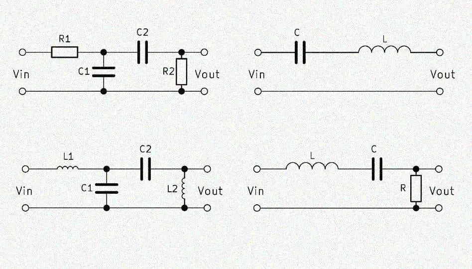
The simple bandpass consists of an RC low-pass and a RC high-pass, each 1st order, so two resistors and two capacitors. High and low pass filters are simply connected in series. The output voltage $V_{out}$ is tapped behind both filters. This variant is also called RC bandpass.
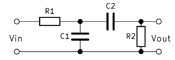
If a low frequency is applied to the input, part of the voltage across the high pass filter will drop. If a high frequency is applied, the voltage drops above the low-pass filter. At a medium frequency, most of the input voltage $V_{in}$ penetrates to the output. The frequency of the input voltage thus determines the height of the output voltage.
RC bandpass – how it works
The RC band pass works through the composition of high pass and low pass filters as well as these two elements. In the high-pass section, the voltage across the resistor is tapped, with the low-pass over the capacitor. The output voltage $V_{out}$ tapped parallel to these two components increases as the input frequency approaches the center frequency. By the ratio of the resistors to the capacitors thus the frequency band can be determined, which passes through the filter.
Formula – band pass filter calculation
Normally two equal resistors and two equal capacitors are selected for one bandpass. Then the band pass filter transfer function applies:
$$ \frac{V_{out}}{V_{in}} = \frac{1}{3 + j \left( \omega R C – \frac{1}{\omega R C} \right)} $$
$\omega$ is the angular frequency of $2 \cdot \pi \cdot f$. $R$ is the resistance and $C$ is the capacitance of the capacitor. This formula can be used to calculate a bandpass.
Calculating bandpass cutoff frequency
With the frequency, the resistances of high and low pass change in the opposite direction. In other words, if the resistance of the high pass increases, then that of the low pass also falls. The cutoff frequencies of both filters are calculated separately and labeled $f_H$ (high) and $f_L$ (low). With these two cutoff frequencies, the center frequency $\mathbf{f_0}$ and the bandwidth $\mathbf{B}$ of the entire filter can then be determined.
The formula for calculating the frequencies is:
$$ f_0 = \frac{1}{2 \pi RC} $$
$$ f_0 = \sqrt{f_H \cdot f_L} $$
$$ B = f_H – f_L $$
RC bandpass filter calculator
The RC bandpass calculator makes it easy for anyone to build a bandpass filter.
Alternative: LC bandpass filter 1st order
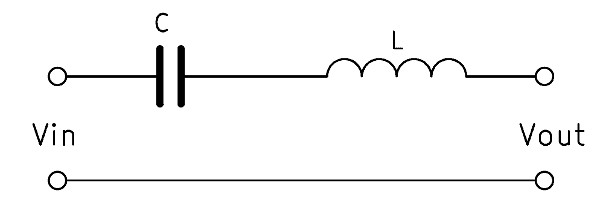
The so-called Butterworth filter simply consists of an inductor with which a capacitor is connected in series. This is the simplest way to build a bandpass filter. The two components filter out very high and very low frequencies.
The formulas for calculating coil and capacitor are:
$$ C = \frac{1}{2 \pi \cdot Z \cdot f_L} $$
$$ L = \frac{Z}{2 \pi \cdot f_H} $$
Passive bandpass filter 2nd order
A 2nd order bandpass is usually built with a circuit of two capacitances and two inductors. The interconnection is identical to the RC bandpass 1st order, only the resistors are replaced by inductors. The filter effect is amplified by this.
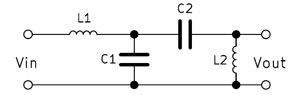
The 2nd order bandpass filter has twice as much edge steepness as a 1st order filter. This means that it reacts twice as fast with changes in frequency and thus filters more strongly. The series connection of several bandpasses, the order can be further increased if necessary.
LC bandpass operation
By replacing the resistors with inductors, the edge steepness increases. Resistors always have the same resistance value independent of frequency. The reason for the change is that the inductance reacts much faster to the change in frequency. As the frequency increases, the inductive reactance $X_L$ of the inductors increases correspondingly.
Formula – calculate bandpass 2nd order
For the ratio of capacitances and inductances:
$$ Z = R_0 = \sqrt{\frac{L_1}{C_2}} = \sqrt{\frac{L_2}{C_2}} $$
$L$ denotes the inductance and $C$ the capacitance of the capacitor.
Calculate cut-off frequency bandpass 2nd order
Again, the capacitive and inductive reactance change in the opposite direction. The cutoff frequency is the frequency at which the two resistance values are identical. If the frequency continues to increase, $X_L$ is larger and $X_C$ gets smaller.
The formula for the upper and lower cutoff frequencies is:
$$ f_{H} = \frac{1}{2 \pi \sqrt{L_1 C_1} \left( -\frac{1}{2} \sqrt{\frac{C_1}{C_2}} + \sqrt{1 + \frac{1}{4} \frac{C_1}{C_2}} \right) } $$
$$ f_{L} = \frac{1}{2 \pi \sqrt{L_1 C_1} \left( +\frac{1}{2} \sqrt{\frac{C_1}{C_2}} + \sqrt{1 + \frac{1}{4} \frac{C_1}{C_2}} \right) } $$
LC bandpass filter calculator
The LC bandpass calculator helps to dimension the components based on the required cutoff frequencies.
Alternative: RLC bandpass
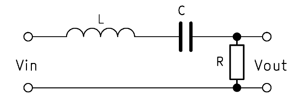
A second order bandpass can also be built with three components in series: an inductor, a capacitor, and a resistor. The output voltage $V_{out}$ is tapped here parallel to the resistor. The operation is similar to the bandpass with resistors and capacitors. The inductive reactance $X_L$ increases along with the frequency, while $X_C$ behaves inversely.
The bandpass transfer function is then:
$$ \frac{V_{out}}{V_{in}} = \frac{1}{\frac{LC}{s^2 + s \frac{1}{RC} + \frac{1}{LC}}} $$
The cutoff frequency of the RLC bandpass is calculated as follows:
$$ f_0 = \frac{1}{2 \pi \sqrt{LC}} $$