A low pass filter only passes signals below its cutoff frequency and weakens the components above it. Here’s how to calculate the different variants of a passive low pass filters. In addition to the formulas, several low pass calculators are available to help.
General information about the low pass filter
A low pass designates a component in electrical engineering that attenuates or blocks high frequencies and allows low frequencies to pass largely unhindered. The term low-pass filter is also common. The term passive merely means that the low pass filter circuit is constructed without an amplifying element. When using an operational amplifier, we have an active low pass.
A low-pass filter is used when fast and abrupt voltage changes at the output are undesirable. It is used, for example, in the construction of woofers to improve their acoustics. Also in network filters, a low pass is often used to remove transmitted parasitic frequencies from the power grid.
Experts distinguish between 1st order low pass and second order low pass filter. We explain the elements of each low pass, how it works and how to calculate a low pass filter. Since these are very complex calculations, we also provide a low pass filter calculator.
Passive low pass 1st order
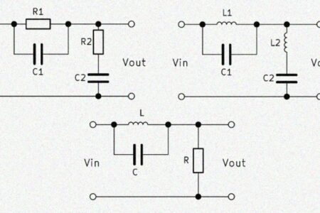
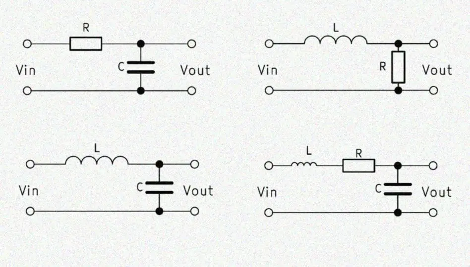
The first order low pass filter consists of a resistor and a capacitor connected in series. Therefore, the term RC low pass is common, where the $R$ stands for the resistor and the $C$ for the capacitor. Parallel to the capacitor, the output voltage $V_{out}$ is tapped. This is important because otherwise it is a high pass filter.
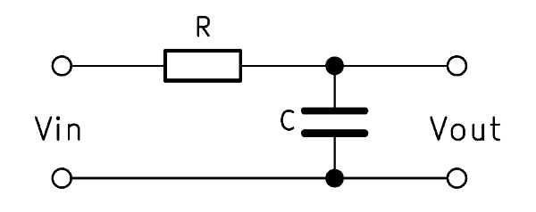
In the case of rapid changes in the input voltage $V_{in}$, virtually no voltage drops across the capacitor, as a result of which the output voltage $V_{out}$ also approaches 0. On the other hand, if there is a slow change in the voltage $V_{in}$, part of the voltage across the capacitor drops. The output voltage $V_{out}$ changes with a time delay. In the following section we want to calculate an RC low pass filter and shed some light on the first order low pass filter transfer function.
RC low pass – how it works
The output voltage $V_{out}$ follows the erratic input voltage $V_{in}$ delayed in time in the same jump height. This is because the changed input voltage briefly passes through the capacitor because the capacitive resistance of the capacitor builds up first. Once the capacitive reactance has reached its new value, the output voltage does not change any further.
With a sinusoidal input voltage, on the other hand, we get a weakened output voltage. The attenuation depends strongly on the frequency due to the slowly developing capacitive reactance of the capacitor. As the input frequency increases, so does the difference between the input and output voltages.
Formula – calculate low pass filter
The formula for calculating an RC low pass filter is:
$$ \frac{V_{out}}{V_{in}} = \frac{1}{\sqrt{1 + (ωCR)^2}} $$
Here, $V_{in}$ stands for the input voltage and $V_{out}$ for the output voltage. The $\omega$ is the angular frequency, ie the product of $2 \cdot \pi \cdot f$ (frequency). $C$ is the capacitance of the capacitor and $R$ is the ohmic resistance.
Calculate cutoff frequency of low pass filter
The ohmic resistance $R$ remains unchanged while the capacitive reactance $X_C$ changes as a function of the frequency. The cutoff frequency denotes the frequency at which the two values are equal, ie $R = X_C$. Thus, at a frequency above the cutoff frequency, $X_C$ is less than $R$, at a lower frequency, $X_C$ is greater than $R$. When operating with the cutoff frequency, 70.71% of the input voltage is output, due to the crest factor $\sqrt{2}$.
The calculation of the cutoff frequency for an RC low pass is done using this formula:
$$ f_c = \frac{1}{2 \pi R C} $$
RC low pass calculator
With the online calculator you can calculate the required components for the desired cutoff frequency.
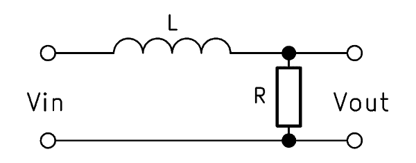
Alternative: RL low pass
If a coil is used instead of the capacitor, a first-order low-pass filter can also be built. For this, however, the output voltage must be tapped parallel to the resistor. The mode of operation is exactly the opposite: the higher the frequency, the greater the proportion of the voltage that drops across the coil.
The formula to calculate output voltage is as follows:
$$ \frac{V_{out}}{V_{in}} = \frac{1}{\sqrt{1+ (\omega \frac{L}{R})^2}} $$
The cutoff frequency is calculated with the following formula for LR low pass:
$$ f_c = \frac{R}{2 \pi L} $$
RL low pass calculator
The online calculator helps calculate the required construction elements for the respective cutoff frequency.
Passive low pass 2nd order
The second-order low pass also consists of two components. With the 2nd order low pass filter, a coil is connected in series with a capacitor, which is why this low pass is also referred to as LC low pass filter. Again, the output voltage $V_{out}$ is tapped parallel to the capacitor. The structure is therefore identical to the low-pass 1st order, it is only the ohmic resistance exchanged for a coil.
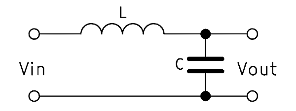
A 2nd order low pass does basically the same function as its 1st order counterpart, but has twice as much slope. So low frequencies can happen while high frequencies are filtered twice as effectively. The difference is caused by the coil. As an inductive load, it reacts much faster to voltage changes than an ohmic resistance.
LC low pass – how it works
The function of the capacitor is exactly the same as in the low-pass 1st order. It is located exactly in the same place and the output voltage is tapped identically. The response to a single, erratic change in input voltage is also comparable. The coil has a resistance near zero as long as a DC voltage is applied.
The difference only becomes apparent when a changing voltage is applied. The coil is more responsive to the increase in frequency than an ohmic resistance. As the frequency increases, the inductive reactance of the coil $X_L$ increases while the capacitance $X_C$ of the capacitor decreases. Thus, changes in the frequency at the input are reflected even more clearly in the level of the output voltage.
2nd order LC low pass filter calculation
The formula for calculating the LC low pass is:
$$ \frac{V_{out}}{V_{in}} = \frac{1}{1 – \omega^2 LC} $$
In the calculation $L$ is added, the inductance of the coil. The ohmic resistance $R$ does not factor. We have provided an LC low pass calculator to make low pass calculation simple.
Calculate cutoff frequency at LC low pass
The inductive resistance $X_L$ increases with frequency while the capacitive reactance $X_C$ is inversely proportional to it – it decreases as the frequency increases. The cutoff frequency is the frequency at which $X_C = X_L$. Thus, at a frequency greater than the cutoff frequency, $X_C$ is less than $X_L$. At a lower frequency, $X_C$ is greater than $X_L$.
The cutoff frequency for an LC low pass is calculated using the following formula:
$$ f_c = \frac{1}{2 \pi \sqrt{LC}} $$
LC low pass calculator
You can calculate the desired cutoff frequency as well as the required components here.