A high pass filter prevents frequencies below its cut-off frequency from passing and lets through signals above it. In this article, you will learn how to calculate the various passive high-pass filters. In addition, you will have access to an online high pass filter calculator.
General information about the high pass filter
A high pass filter circuit designates a circuit in electrical engineering with the purpose of attenuating or blocking low frequencies. High frequencies, however, should be as unhindered as possible. The term high pass filter is also common. The high pass is passive if no amplifying element is used. Otherwise, it is considered active.
A high pass is used where low frequencies are undesirable and therefore should be filtered out. Examples include the construction of tweeters or the high-frequency signal transmission via power lines. The low frequencies in these cases would make the signal almost unusable for further processing and must be eliminated.
Electricians distinguish between a high pass 1st order and 2nd order. High order high passes are achieved by switching lower orders in series. We explain how the high pass works and how a high pass can be calculated. In addition, we provide a high pass calculator for the sake of simplicity.
Passive first order high pass filter
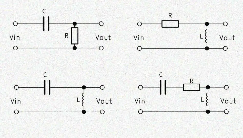
The simple high pass of the 1st order is built up with a capacitor and a resistor connected in series. Aspects of a high pass filter schematic follow. The capacitor has the abbreviation $C$ and the resistor $R$, which is why the abbreviation $RC$ high pass is often used. A CR high pass is also often called, but designates the same circuit. The output voltage $V_{out}$ must here be tapped parallel to the resistor, otherwise we would have a low-pass filter.
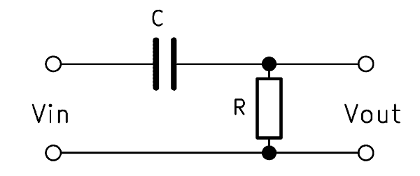
When a high frequency is applied to the input, an imperceptibly small voltage drops across the capacitor. The output voltage $V_{out}$ is thus almost identical to the input voltage $V_{in}$. However, if a low frequency is present, part of the voltage across the capacitor will drop. As a result, the output voltage drops parallel to the resistor with a time delay.
RC high pass – how it works
In a single, erratic change in the input voltage $V_{in}$, there is a short voltage spike of the output voltage $V_{out}$. This is because the capacitor lets the changed voltage pass for a short time. Its capacitive reactance $X_C$ takes a short time to build up.
However, if the input voltage has a frequency, $X_C$ depends on the level of that frequency. As the frequency increases, the voltage drop across the capacitor decreases. Consequently, the output voltage increases. At a low frequency, $X_C$ increases and more voltage drops across the capacitor. The output voltage $V_{out}$ decreases.
Formula – RC high pass filter calculation
The basic formula for calculating an RC high pass is:
$$ \frac{V_{out}}{V_{in}} = \frac{R}{Z} $$
The following applies to the impedance Z:
$$ Z = \sqrt{R^2 + X_C^2} $$
The RC high pass filter transfer function is calculated according to:
$$ \frac{V_{out}}{V_{in}} = \frac{1}{\sqrt{1 + \frac{1}{(2 \pi f R C)^2}}} $$
$R$ stands for the ohmic resistance. $f$ is the frequency and $C$ is the capacitance of the capacitor.
Calculate cutoff frequency of high pass
The capacitive reactance $X_C$ decreases as the frequency increases, while the ohmic resistance $R$ remains constant. The cutoff frequency $f_c$ is the frequency at which the resistances are equal. Consequently, at a frequency above $f_c$, $R > X_C$ and at a lower frequency $X_C > R$.
With this formula, the cutoff frequency can be calculated with an RC high pass:
$$ f_c = \frac{1}{2 \pi R C} $$
RC high pass calculator
The online calculator helps you to dimension the components for the desired cutoff frequency.
Alternative: RL high pass
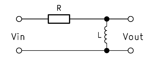
The RL high pass is also a 1st order filter. Instead of the capacitor, however, an inductor is used and the output voltage tapped parallel to this. The mode of operation is exactly the opposite: the inductive reactance $X_L$ increases along with the frequency.
The formula for the calculation is:
$$ \frac{V_{out}}{V_{in}} = \frac{1}{\sqrt{1 + (2 \pi f L)^2}} $$
The cutoff frequency for a RL high pass results from:
$$ f_c = \frac{R}{2 \pi L} $$
RL high pass calculator
The online calculator helps you to dimension the components for the desired cutoff frequency.
Passive second order high pass filter
The structure is identical to the high-pass filter 1st order, except that the ohmic resistance is replaced by an inductance. Consequently, in the 2nd order high pass filter, a coil is connected in series with a capacitor. The term LC high pass is therefore common. The output voltage $V_{out}$ is tapped here over the inductive load.
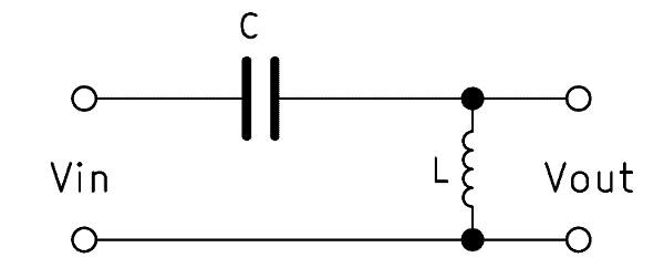
A 2nd order high pass filters the low frequencies twice as effectively as a 1st order high pass. The edge is twice as steep. The difference comes from the coil, which, unlike the capacitor, reacts quickly to high frequencies.
LC high pass operation
The function of the capacitor remains unchanged. At a low-frequency input voltage, it forms a high capacitive reactance $X_C$. A sudden change therefore causes a momentary voltage spike at the output, because the capacitor’s reaction is delayed.
When applying a sinusoidal voltage, however, the coil fulfills its purpose. The capacitor forms a resistor at low frequencies and allows high frequencies through. The coil, on the other hand, reacts immediately to an increase in frequency and forms an inductive reactance $X_L$. In contrast to the capacitor, their resistance increases together with the frequency. This ensures a faster and stronger response to frequency increases.
Formula – calculate high pass 2nd order
The formulas for calculating an LC high pass are:
$$ L = \frac{Z}{2 \pi f} $$
$$ C = \frac{1}{2 \pi f Z} $$
$$ f = \frac{1}{2 \pi \sqrt{LC}} $$
$$ Z = \sqrt{\frac{L}{C}} $$
The associated high pass transfer function is:
$$ \frac{V_{out}}{V_{in}} = \frac{X_L}{X_L + X_C} $$
$L$ stands for the inductance of the coil, $Z$ for the impedance and $C$ for the capacitance of the capacitor.
Calculate cutoff frequency of 2nd order high pass
As described above, capacitive and inductive reactances always change in opposite directions. At the cutoff frequency, the resistors are identical. It is therefore: $X_L = X_C$. At a higher frequency, therefore, $X_C > X_L$ and at a lower frequency $X_C < X_L$.
The formula for calculating the cutoff frequency is:
$$ f_c = \frac{1}{2 \pi \sqrt{LC}} $$
LC high pass filter calculator
The online calculator helps you to dimension the components for the desired cutoff frequency.