A band stop filter filters a defined frequency band out of the signal. The terms “band reject filter” or “notch filter” are common too. In this article, you will find different circuit variants of a passive bandstop filter. In addition to the formulas for calculating the stop band, the article contains practical online calculators to aid in dimensioning.
General information about the band stop filter
The bandstop circuit or bandstop filter is an electrical circuit for filtering frequencies. The name band stop has a circuit to attenuate a frequency band or blocks. Frequencies outside of this band should pass with as little loss as possible. A passive band stop filter is one where no amplifying components such as transistors are used in the circuit. If there are such, it is an active band stop filter.
One possible use of band stop filters is to improve the signal transmission. Here, the circuit could filter out signals of a particular frequency range if they are unwanted and would interfere with the transmission. Previously, there was the “metering impulse” in the phone line that could hinder modems in their function. With a passive bandstop, this impulse was suppressed.
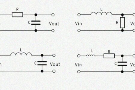
A passive band stop filter basically consists of the parallel connection of a high pass and a low pass. The order of a band stop filter indicates how large the range of the frequency transition is. The higher the order, the smaller this transition range. We will explain how it all works and how to calculate a band stop filter. In addition, we offer a band stop filter calculator, which makes using the formulas easier.
Passive bandstop filter 1st order
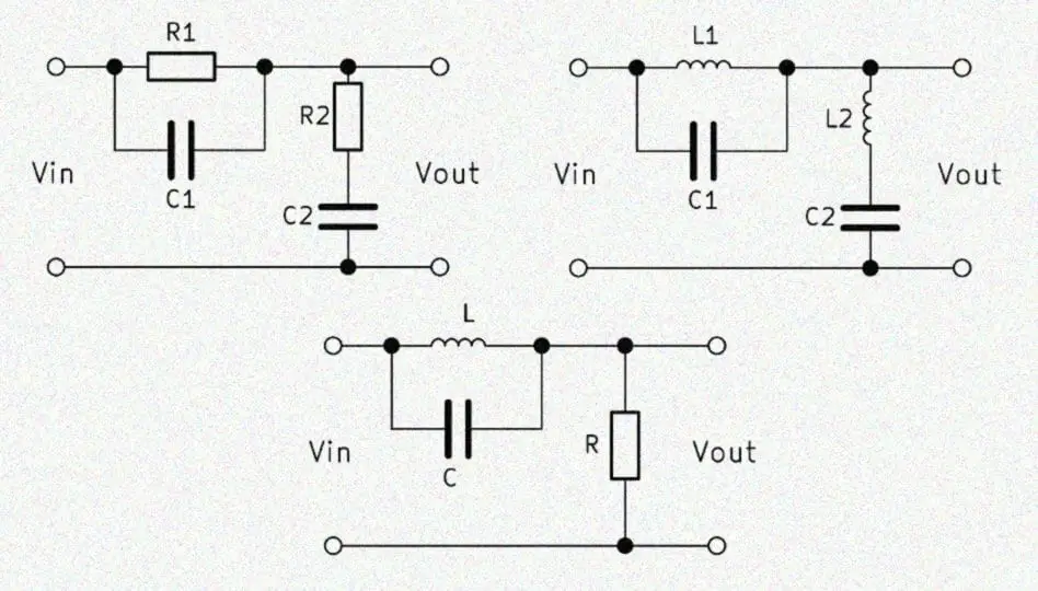
A bandstop 1st order is created in principle by the parallel connection of a high pass and a low pass of the 1st order. Thus, two ohmic resistors and two capacitors are needed, which is why this circuit is also called RC band stop filter. The output voltage $V_{out}$ is tapped in the middle of the two circuits.

With a frequency at the input, the voltage drop across the two circuits changes, and so does the ratio between input and output voltage respectively. High frequencies pass through the high-pass filter, and low frequencies – through the low-pass filter. By dimensioning the resistors and capacitors, the center region is determined in which there is almost no voltage at the output.
RC band stop – how it works
The band stop filter uses the advantages of high and low pass. At a high frequency at the input, a high output voltage $V_{out}$ drops at the high-pass and at a low input frequency at the low-pass. The parallel connection of these two elements allows high and low frequencies to pass through almost unhindered.
In the middle there is a superimposed area of both filters, in which little voltage drops at the output. The input voltage is simultaneously attenuated by the high-pass and low-pass filters. The center of this superimposed area is called the center frequency $f_0$. Due to the characteristics of the band stopper is sometimes referred to as a bathtub filter.
Formula to calculate the band stop filter
In the simple RC band stop, the resistors and capacitors are usually the same size. The band stop filter transfer function is based on the following formula in this case:
$$ A = \frac{1 – (\omega RC)^2}{1 + 4 \omega RC – (\omega RC)^2} $$
$R$ is the ohmic resistance and $C$ is the capacitance of the capacitors. The $\omega$ is the angular frequency of $2 \cdot \pi \cdot f$.
Band stop calculate cutoff frequency
A band stop filter has two cut-off frequencies: one for the high pass and one for the low pass. These two cutoff frequencies are calculated separately. They both result from the relationship:
$$ \frac{V_{out}}{V_{in}} = 70,7 \% $$
In addition to the two cutoff frequencies, the calculation of the center frequency f0 is also interesting. It forms the geometric mean of the upper limit frequency $f_{H}$ and the lower limit frequency $f_{L}$. The formula is:
$$ f_0 = \sqrt{f_{H} \cdot f_{L}} $$
RC band stop filter calculator
The online calculator helps to design the components for the desired center frequency.
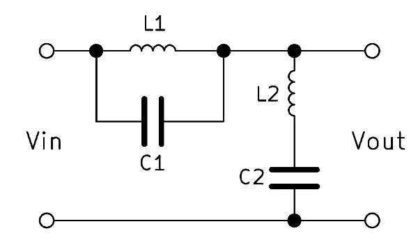
Band stop filter 2nd order
A band stop filter (band reject filter) of the 2nd order is constructed identically to the filter of the 1st order. The replacement of the ohmic resistance against an inductance increases the order. A higher order means that the filter effect becomes stronger and the transition areas smaller. A 2nd order filter has twice as much edge steepness as a 1st order filter. By interconnecting further band stop filters, the order can be increased even further.
Functions of LC band reject filter
Like the construction, the functions are also very similar to the 1st order band stop filter circuit. However, the inductance also has a reactance $X_L$, which is inversely proportional to the capacitive reactance $X_C$. This means that as the frequency increases, the reactance of the capacitor decreases and the reactance of the coil increases simultaneously. As a result, the filter effect is significantly increased and frequency changes at the input can be seen more clearly at the output.
Formula – band reject filter 2nd order
The following applies to the LC band stop filter:
$$ Z = R_0 = \sqrt{\frac{L_1}{C_2}} = \sqrt{\frac{L_2}{C_1}} $$
The band stop transfer function of the 2nd order is:
$$ T(s) = \frac{1 + \frac{s^2}{\omega_0^2}}{1 + s \frac{B}{\omega_0^2} + \frac{s^2}{\omega_0^2}} $$
Cut-off frequency LC band stop calculation
Again, there is a lower and an upper limit frequency. These are calculated using the following formulas:
$$ f_{L} = \frac{1}{2 \pi \sqrt{L_1 C_1} \left( -\frac{1}{2} \sqrt{\frac{C_2}{C_1}} + \sqrt{1 + \frac{1}{4} \frac{C_2}{C_1}} \right) } $$
$$ f_{H} = \frac{1}{2 \pi \sqrt{L_1 C_1} \left( +\frac{1}{2} \sqrt{\frac{C_2}{C_1}} + \sqrt{1 + \frac{1}{4} \frac{C_2}{C_1}} \right) } $$
LC band stop filter calculator
The online calculator helps with the design of components for the construction of a LC band stop filter.
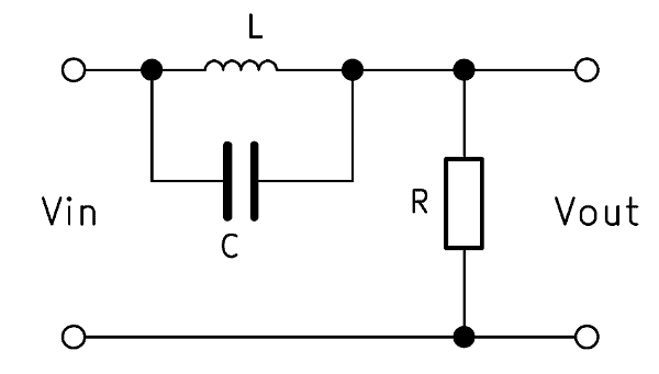
Alternative: RLC stop band circuit
A second-order band stop filter can also be constructed with a resistor, capacitor and inductance circuit. The structure is therefore identical to a RLC band pass. However, the output voltage $V_{out}$ is tapped here in parallel to the inductor and capacitor. The mode of operation also remains the same, since the inductance and capacitor reactances change in opposite directions.
The RLC band stop is calculated using the following formula:
$$ \frac{V_{out}}{V_{in}} = \frac{1 – \frac{\omega^2}{\omega_2^2}}{1 – \frac{\omega^2}{\omega_2^2} + j \frac{\omega}{\omega_1}} $$