The LC filter, also called the LC filtering element, designates a circuit with an inductance L and a capacitance C in electrical engineering. As an LC filter, the two components are connected either in series or in parallel. The LC filter cutoff frequency is a key element of this. There is a relationship between input frequency and output voltage because both components react differently to changes in voltage.
This article section explains the LC filter design in detail, as well as how an LC filter works. To this end, it is necessary to understand the electronic components coil and capacitor a little better. Afterwards we will clarify how to calculate an LC filter, explain about the LC filter design tool and provide an LC filter calculator. This tool can calculate LC filter transfer function as well.
How inductance and capacitance work
Three types of load resistance are distinguished in electrical engineering: ohmic, inductive and capacitive resistance. Ohmic resistance is independent of the frequency and always remains the same. In contrast, inductive and capacitive resistances change with the frequency of the applied voltage. This is due to the inductive reactance $X_L$ and the capacitive reactance $X_C$.
If an alternating current flows through a coil, then a magnetic field is built up and taken down in it. The electronic engineer speaks of induction. The induced voltage counteracts the applied voltage, resulting in the inductive reactance $X_L$. The effect of induction increases with increasing frequency. The current flow in the coil is always delayed, so the voltage always rushes afterwards.
The capacitor is, in principle, a battery with a very small capacity. It can be charged and discharged again. The capacitor acts like a nearly infinite resistance in a DC circuit. In an AC circuit, however, it is permanently charged and discharged by the alternating current direction. Basically, the current does not really flow through the capacitor. During this continuous charging and discharging, the capacitive reactance $X_C$ is created. The higher the frequency, the shorter the charging cycles of the capacitor and the lower its reactance.
LC filter – circuit variants
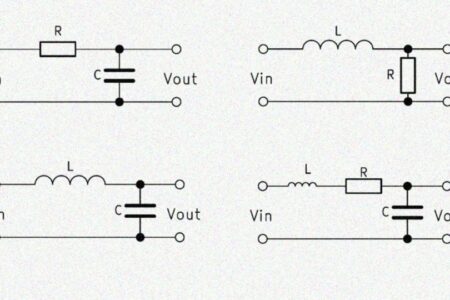
Through the interconnection of coil and capacitor, a circuit is constructed whose output voltage changes with the frequency of the input voltage. It can be built with an identical circuit different filters. The type of filter depends on whether it is a series or parallel connection and at which point the output voltage is tapped. Frequently used LC filter circuits are high pass, low pass, band pass and band stop filters.
Low pass
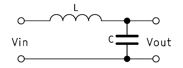
The LC low pass is created by connecting the two elements in series, when the output voltage across the capacitor is tapped. At a high frequency, the reactance of the capacitor decreases and the reactance of the coil increases. Consequently, only a very small output voltage remains. With decreasing frequency, however, the capacitive reactance of the capacitor increases and so does the tapped output voltage. Our LC low pass calculator can calculate a 2nd order low pass.
High pass
The LC high pass can pass high frequencies while weakening or blocking low frequencies. For this purpose, the output voltage across the inductance is tapped at a series circuit of inductance and capacitance. When the frequency of the input voltage is low, the voltage across the capacitor drops and the output voltage remains very small. In contrast, as the frequency increases, more and more voltage across the inductance drops and can be used as the output voltage. The LC high pass is also 2nd order and can be determined using the LC high pass calculator.
Band pass
An LC band pass is created by an LC series connection and an LC parallel circuit. These two elements are connected in series and the output voltage across the parallel circuit is tapped. The interaction of the two elements results in an output voltage which is highest in a certain frequency band. Above and below this frequency band, the output voltage decreases. The midpoint of this band is called the center frequency. Since the calculation is complicated, we have provided an LC band pass calculator.
Band stop
The LC band stop is built up identically to the LC band pass. Only the output voltage has to be tapped via the series connection. The band stop behaves opposite to the band pass, weakening or blocking a frequency band. Frequencies can be higher or lower. Again, the center frequency is the center of the curve in the graph. Calculating a band-stop LC filter is complex, which is why the LC band stop calculator can be of great help.
LC filter application areas
The effects of coil and capacitor are primarily used to filter frequencies. For example, when building loudspeakers, the other frequencies can be filtered on the high, mid and woofers. This significantly improves the sound, as the woofer cannot reproduce high notes and vice versa.
Devices for wireless transmission of signals often generate unwanted frequencies that are not to be emitted. These can be filtered out with a correctly dimensioned LC filter element before being forwarded to the antenna. For large transmission power, such filters are mandatory.
Radio receivers only need the frequency bands that they are supposed to receive. Other frequencies only worsen the signal quality in the form of background noise such as noise and crackling. Eventually, the device starts to transmit signals that it picks up from other frequencies. With the LC filter as band pass, the transmitted frequency number can be limited and the signal quality improves.
Another relevant example of a frequency filter is the station search with radios. If we want to listen to a certain station, we set the radio to its frequency. All other frequencies are filtered out in order to ensure trouble-free reception. In transition areas, an overlay of the two adjacent transmitters is often heard.