Ohm’s Law is a fundamental principle in physics and electrical engineering. It describes the relationship between electrical voltage, current, and resistance in an electrical circuit. Here you will find all the details about Ohm’s Law, including formulas, applications, and examples.
Fundamentals of Ohm’s Law
Ohm’s Law is a fundamental principle in electrical engineering that describes the relationship between current (I), voltage (U), and resistance (R).
The basic formula for Ohm’s Law is:
$$ U = R \cdot I $$
Voltage (U) is measured in Volts (V), current (I) in Ampere (A), and electrical resistance (R) in the unit of Ohm (Ω).
The unit of resistance, Ohm (Ω), was named after the German physicist Georg Simon Ohm, who discovered Ohm’s Law in the 19th century.
Ohm’s Law Formulas
Thanks to Ohm’s Law, you only need to know two of the three quantities, voltage, current, or resistance, to calculate the third one.
You can rearrange the formula according to the quantity you want to calculate:
Calculating Voltage
For voltage calculation, multiply resistance by current:
$$ U = R \cdot I $$
Calculating Current
For current calculation, divide voltage by resistance:
$$ I = \frac{U}{R} $$
Calculating Resistance
For resistance calculation, divide voltage by current:
$$ R = \frac{U}{I} $$
Series and Parallel Connections
In real circuits, there are often multiple resistors in an electrical circuit. These resistors can be connected either in series or in parallel.
There are different formulas for calculating the total resistance for each type of connection:
Practical Applications
In practice, Ohm’s Law and its applications are encountered in many electrical and electronic components, ranging from light bulbs to complex circuits. Here are some common applications.
Current-Limiting Resistor
Current-Limiting Resistors are used to limit the maximum current through a component. For example, LEDs require a series resistor to set the correct current.
→ Here you can find all the details for calculating an LED resistor
Internal Resistance
Electrical sources like batteries or power supplies have an internal resistance. This resistance has a significant impact on the output power of a voltage source.
→ Here you can find all the information on calculating internal resistance
Voltage Divider
A voltage divider is a circuit that converts an input voltage into a lower output voltage. It consists of two or more resistors connected in series. The output voltage in a voltage divider is proportional to the respective resistance values.
→ Here you can find all the details for calculating a voltage divider
Current Divider
The counterpart to the voltage divider is the current divider. A current divider splits an input current into two or more output currents through parallel resistors.
→ Here you can find all the details for calculating a current divider
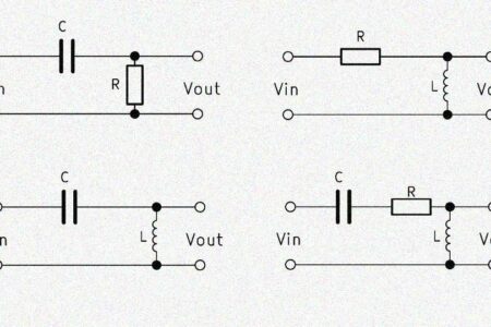
Current-Voltage Characteristics
The current-voltage characteristic, also known as the I-V characteristic, is a graph that shows the relationship between electric current (I) and applied voltage (U) for a specific electrical resistance (R) in a circuit.
In the case of an ohmic resistor, the relationship between current and voltage is linear, and the proportionality factor of the I-V graph is exactly equal to the resistance R.
However, Ohm’s Law only applies to ohmic resistors, which exhibit a linear relationship between voltage and current. Non-ohmic components, such as a semiconductor diode, do not have a linear I-V characteristic.
In such cases, resistance varies with voltage, and the I-V characteristic displays a curved relationship between current and voltage.
Ohm’s Law vs. Incandescent Bulb
When operating an incandescent bulb, an interesting phenomenon related to Ohm’s Law can be observed.
Firstly, the brightness of an incandescent lamp depends on the applied voltage. The higher the voltage, the higher the current flowing through the bulbs filament.
However, at a certain point, the temperature of the filament increases, which in turn affects the filament’s resistance. Since the resistance of metals generally increases with temperature, the resistance of the filament cannot be considered constant.
Here, the resistance exhibits a non-linear behavior dependent on factors such as temperature. Therefore, a higher voltage does not always lead to a proportionally higher current, as predicted by Ohm’s Law for constant resistances.
History of Ohm’s Law
Ohm’s Law was discovered in 1826 by Georg Simon Ohm and is a fundamental relationship in electrical engineering. It describes the relationship between current, voltage, and resistance in an electrical circuit.
Georg Simon Ohm was a German physicist and mathematician who primarily focused on the science of electricity.
In his research, he found that the electric current flowing through a conductor is directly proportional to the applied electric voltage. Conversely, electrical resistance remains constant when it is independent of voltage and current magnitude.
Ohm’s Law is of central importance in electrical engineering as it forms the basis for calculating current, voltage, and resistance in electrical circuits.