This site explains the exact operation of an RC filter and its individual components. Below we mention some possibilities of the RC circuit and typical applications. Then we explain how an RC filter can be calculated and also provide an RC circuit calculator for the most common variants of the RC circuit.
The RC filter or RC filter element in electrical engineering refers to a circuit with a resistance R and a capacitance C. The two components can be connected either in parallel or in series. A combination of several resistors and capacitors is possible.
Due to the properties of the components, a relationship between the frequency at the input and the voltage at the output is achieved. This effect can be meaningfully used in electronic circuits that work differently depending on the frequency. Therefore, only voltages with certain frequencies are applied here.
How the components work
The resistance of the wire is ignored in most calculations due to its minimal size. The ohmic resistance R always remains constant. It does not change its value with differences in voltage and current. Frequency changes also have no effect on R.
The capacitor C, however, works like a battery with a very small capacity. With DC voltage, it will charge itself and represent a break in the circuit when fully charged. However, if it is connected to an AC voltage, it forms a capacitive reactance $X_C$, which changes depending on the voltage. This effect arises from the fact that the capacitor is permanently charged and discharged by changing the poles. The lower the frequency, the longer the charge cycles and the larger the capacitive reactance $X_C$.
RC filter resistance, capacity and time constants
When calculating the RC filter, the resistance and capacitance are most important. The interaction of these two elements results in the desired filter effect. Depending on the interconnection, the formulas change for the calculation, but these two variables always play a role.
The function of the capacitor also makes the time constant of the RC filter important. This is calculated based on resistance and capacity and indicates the required charging time. Depending on the circuit, the RC filter can be calculated according to different formulas, but the time constant of the RC filter is calculated identically for each one.
Online RC calculators
It is easier to work with the circuits using our RC filter calculators. Due to the different connections of resistor and capacitor, various filters can be realized. It depends on whether the components are connected in series or in parallel and at which point the output voltage is tapped. Frequently used options are high pass, low pass, band pass and band stop, which we want to calculate as an RC circuit.
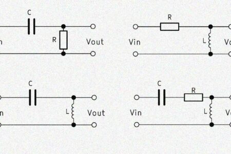
High pass
An RC high-pass filter is created by the series connection of the two components, whereby the output voltage is tapped above the ohmic resistance. A simple RC high pass is a 1st order high pass. The resistance of the capacitor increases with decreasing frequency and vice versa. An RC filter cutoff frequency calculator would be very useful here. The smaller the resistance of the capacitor, the greater the voltage drop across the ohmic resistance. Consequently, the output voltage increases along with the frequency at the input. The corresponding section explains how to calculate an RC filter element.
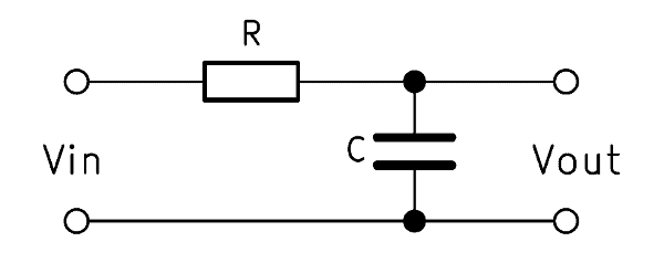
Low pass
The structure of the RC low-pass filter and RC high-pass filter is identical, but here the output voltage across the capacitor is tapped. This gives us the exact opposite effect. The resistance of the capacitor increases with decreasing frequency. The greater the resistance, the greater the voltage drop and the output voltage. The RC low pass is also a low pass of the 1st order. The accompanying section explains how to calculate an RC circuit.
Band pass
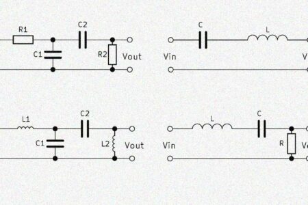
The RC band pass is created by a combination of two RC filters. An RC series circuit and an RC parallel circuit are connected in series. The output voltage is tapped via the parallel connection. This circuit makes the output voltage in a frequency band the highest. The middle of this band is called the center frequency. At higher or lower frequency, the output voltage drops. Our calculator makes it easy to calculate the RC filter.
Band stop
The RC band stop is the counterpart to the band pass and is built exactly the same way. The area through which the band pass passes is attenuated or blocked during band-stop. For this purpose, the output voltage across the series circuit is simply tapped. Here, the center frequency is the center of the locked area. With our RC frequency calculator, it is easier to determine a band stop filter as an RC element.
RC filter application areas
The filtering of frequencies is used in speakers to improve the sound quality. The speakers can only reproduce the signals in the correct frequency range. Sounds on other frequencies would be distorted; one hears squeaking or scratching. The tweeter is therefore a high pass and the woofer a low pass. The midrange therefore uses the bandpass.
All radio signals operate on a certain frequency, which is usually in the range of many megahertz. For mobile stations, for example, the frequencies are sold to the providers to ensure trouble-free operation. The signal can be transmitted only if the transmitter and receiver work on the same frequency. To minimize interference, unwanted frequencies are filtered out before transmission. For large transmitters, the filtering of the transmitted signals is required by law.
The receiver of the signal should also be provided with a filter so that unwanted signals from other frequency ranges are not received. These could be noticeable in noise or even disrupt the actually received signal. When receiving a certain signal frequency, for example, a bandpass filter could be dimensioned quite accurately and thus exclude interference. A common example of this is the station search for radios.
Filter elements are often used in network devices. In most cases, these remove high-frequency signals that inadvertently get into the power line and are transmitted. Although the signals have no influence on the transmission of the mains voltage, they can cause disturbances in other devices. One speaks of net filters in this special case.